 | ||||||||||||||||||||||||||||||||||||||||||||||||||||||||||||||||||||||||||||||||||||
| NPHS 1530: Analytics | ||||||||||||||||||||||||||||||||||||||||||||||||||||||||||||||||||||||||||||||||||||
| Reliability | ||||||||||||||||||||||||||||||||||||||||||||||||||||||||||||||||||||||||||||||||||||


| ||||||||||||||||||||||||||||||||||||||||||||||||||||||||||||||||||||||||||||||||||||
   | ||||||||||||||||||||||||||||||||||||||||||||||||||||||||||||||||||||||||||||||||||||
|
Ā COMPLEX SERIES/PARALLEL SYSTEM RELIABILITY
Many systems are seldom purely series or parallel combinations of components, but are mixtures of series and parallel components connected in series or parallel. The figure below shows such a system. | ||||||||||||||||||||||||||||||||||||||||||||||||||||||||||||||||||||||||||||||||||||
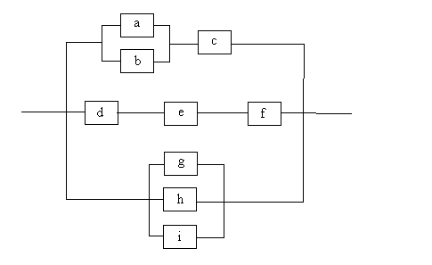 | ||||||||||||||||||||||||||||||||||||||||||||||||||||||||||||||||||||||||||||||||||||
| The reliability for the complex system shown above can be calculated by identifying the portions of the system that are purely series or parallel combinations and by replacing them with a single component whose reliability is equivalent to the combination. This process is repeated until the complex system is reduced to a single component. The calculated reliability of this component is the reliability of the system. In the above example, components a and b can be combined in parallel using | ||||||||||||||||||||||||||||||||||||||||||||||||||||||||||||||||||||||||||||||||||||
| Rab = 1 - (1 - ra) * (1 - rb) | ||||||||||||||||||||||||||||||||||||||||||||||||||||||||||||||||||||||||||||||||||||
| d, e and f can be combined in series | ||||||||||||||||||||||||||||||||||||||||||||||||||||||||||||||||||||||||||||||||||||
| Rdef = rd * re * rf | ||||||||||||||||||||||||||||||||||||||||||||||||||||||||||||||||||||||||||||||||||||
| components g, h and i can be combined in parallel. | ||||||||||||||||||||||||||||||||||||||||||||||||||||||||||||||||||||||||||||||||||||
| Rghi = 1 - (1 - rg) * (1 - rh) * (1 - ri) | ||||||||||||||||||||||||||||||||||||||||||||||||||||||||||||||||||||||||||||||||||||
| These combinations are replaced by a single component whose reliability is equal to the reliability of the combination. | ||||||||||||||||||||||||||||||||||||||||||||||||||||||||||||||||||||||||||||||||||||
A Partially Reduced Complex System
| ||||||||||||||||||||||||||||||||||||||||||||||||||||||||||||||||||||||||||||||||||||
| Next, the previously combined component ab can be combined with component c in series producing the network below. | ||||||||||||||||||||||||||||||||||||||||||||||||||||||||||||||||||||||||||||||||||||
A Partially Reduced Complex System
| ||||||||||||||||||||||||||||||||||||||||||||||||||||||||||||||||||||||||||||||||||||
|
Finally, the reduced components abc, def and ghi can be
combined in parallel to produce a single component (abcdefghi) whose
reliability is equal to the reliability of the original complex system.
In the complex system example above, let us assume the reliabilities of components a, c, f and i are .9, the reliabilities of components b and h are .95, the reliabilities of components d and g are .85 and the reliability of component e is .8. Following along with the system series/parallel reduction techniques outlined above, the parallel combination of components a and b (new component ab) has a reliability of .995; the series combination of components d, e and f (def) has a reliability of .612 and the parallel combination of components g, h and i result in a component (ghi) whose reliability is .99925. Next, combining ab with c in series gives a reliability of .8955 for new component abc. Finally, combining the previously reduced component abc, def and ghi in parallel gives a system reliability of .99997. Note that the order that we apply the series and parallel combination rules does not matter as long as the combinations are legitimate.Ā For example, if in Figure 8.8 we elect to combine components def and ghi in parallel and then combine components ab and c in series we would get the reduced network shown in the figure below. 
Ā When these two components are combined in parallel the total system reliability is the same as before: Ā .99997. The figure below gives a complex system example problem for the evacuation from Washington, DC to Harrisburg, PA. | ||||||||||||||||||||||||||||||||||||||||||||||||||||||||||||||||||||||||||||||||||||
A Routing Complex System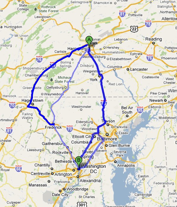
| ||||||||||||||||||||||||||||||||||||||||||||||||||||||||||||||||||||||||||||||||||||
| The reliability network schematic for this example is: | ||||||||||||||||||||||||||||||||||||||||||||||||||||||||||||||||||||||||||||||||||||
A Routing Complex System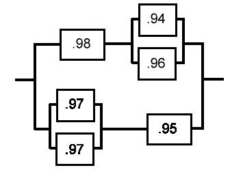
| ||||||||||||||||||||||||||||||||||||||||||||||||||||||||||||||||||||||||||||||||||||
|
The System Reliability isĀ
.823372
The experienced emergency analyst can get a good idea of the reliability of a system such as this one without going through laborious calculations by applying the series heuristics and the parallel heuristics.Ā By applying the second series heuristic to the entire system, we see that the reliability of this system must be less than .85 since this first component of the system is in series with the rest of the system. Ā To estimate the true system reliability we need to investigate the rest of the system.Ā To make this process clear, we will proceed through the analysis in steps.
| ||||||||||||||||||||||||||||||||||||||||||||||||||||||||||||||||||||||||||||||||||||
| Non Series/Parallel Systems
Systems can be constructed of components that are neither in series or parallel nor are reducible to series or parallel subsystems.Ā Perhaps the simplest example of this is the mesh network.Ā The figure below shows a simple four node mesh network. 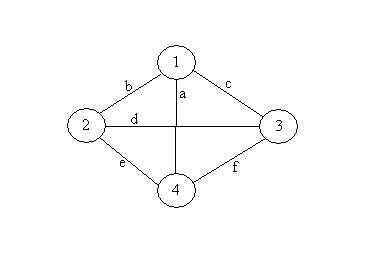
If only one of the components has failed, the network system will still operate. The probability of one failure is r4(1-r) for each of the five cases in which ther is only one failure. Ā Similarly if any two components fail, the network system is still operable.Ā There are ten combinations where two components are failed and each has a probability of r3(1-r)2. The situation where three components have failed is a little more complex.Ā For three failed components, there are ten combinations of component failures. Ā The table below shows the states for the bridge network where three of the components have failed.Ā W is used to indicate that the component is working and F is used to indicate that the component has failed.Ā O is used to show that the system is operating and N is used where the system is not operating.
| ||||||||||||||||||||||||||||||||||||||||||||||||||||||||||||||||||||||||||||||||||||
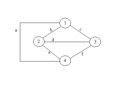
| Only two of the states where two components are operating contribute to the reliability of the network system. | ||||||||||||||||||||||||||||||||||||||||||||||||||||||||||||||||||||||||||||||||||||
| Their probabilities are r2(1-r)3 each.Ā None of the states where four or five of the components have failed result in the network operating and thus do not contribute to reliability.Ā The reliability of the bridge network is therefore: | ||||||||||||||||||||||||||||||||||||||||||||||||||||||||||||||||||||||||||||||||||||
| r5 + 5r4(1-r) + 8r3(1-r)2+2r2(1-r)3 | ||||||||||||||||||||||||||||||||||||||||||||||||||||||||||||||||||||||||||||||||||||
| This reliability in parallel with link a's reliability is the reliability for the mesh network.Ā The reliability of complex networks that are not decomposable into pure series or parallel components can be found in a similar manner. | ||||||||||||||||||||||||||||||||||||||||||||||||||||||||||||||||||||||||||||||||||||
| Complex Example | ||||||||||||||||||||||||||||||||||||||||||||||||||||||||||||||||||||||||||||||||||||
| Tesla Power Supply | ||||||||||||||||||||||||||||||||||||||||||||||||||||||||||||||||||||||||||||||||||||
| The 85 kWh battery pack weighs 1,200 lb (540 kg) and contains 7,104 lithium-ion battery cells in 16 modules wired in series (14 in the flat section and two stacked on the front). Each module contains 6 groups of 74 cells wired in parallel. | ||||||||||||||||||||||||||||||||||||||||||||||||||||||||||||||||||||||||||||||||||||
| The reliability of a module is: | ||||||||||||||||||||||||||||||||||||||||||||||||||||||||||||||||||||||||||||||||||||
| rM = 1-( 1 - (rBattery)444. | ||||||||||||||||||||||||||||||||||||||||||||||||||||||||||||||||||||||||||||||||||||
| The reliability of a battery pack is: | ||||||||||||||||||||||||||||||||||||||||||||||||||||||||||||||||||||||||||||||||||||
| rP = rM16. | ||||||||||||||||||||||||||||||||||||||||||||||||||||||||||||||||||||||||||||||||||||
 Panasonic 3.7v Protected Button Top Battery | ||||||||||||||||||||||||||||||||||||||||||||||||||||||||||||||||||||||||||||||||||||
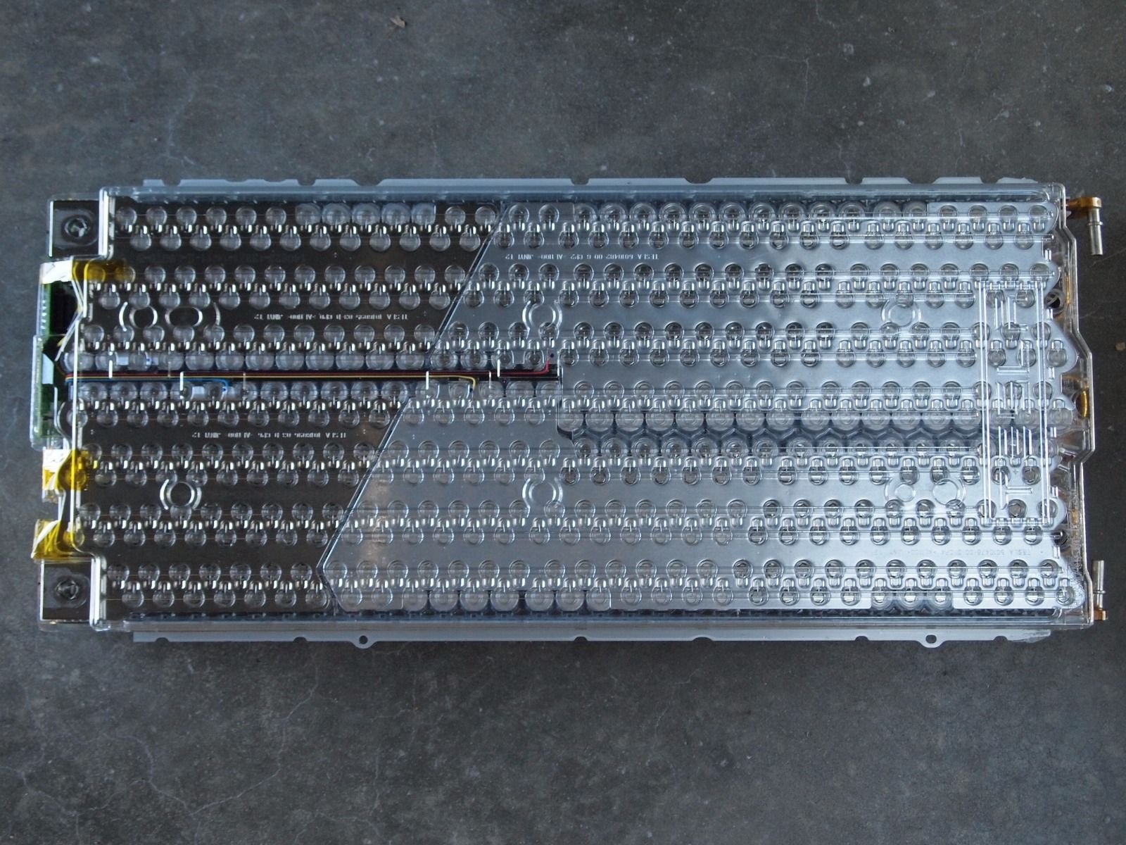 Top View of Tesla Battery Assembly | ||||||||||||||||||||||||||||||||||||||||||||||||||||||||||||||||||||||||||||||||||||
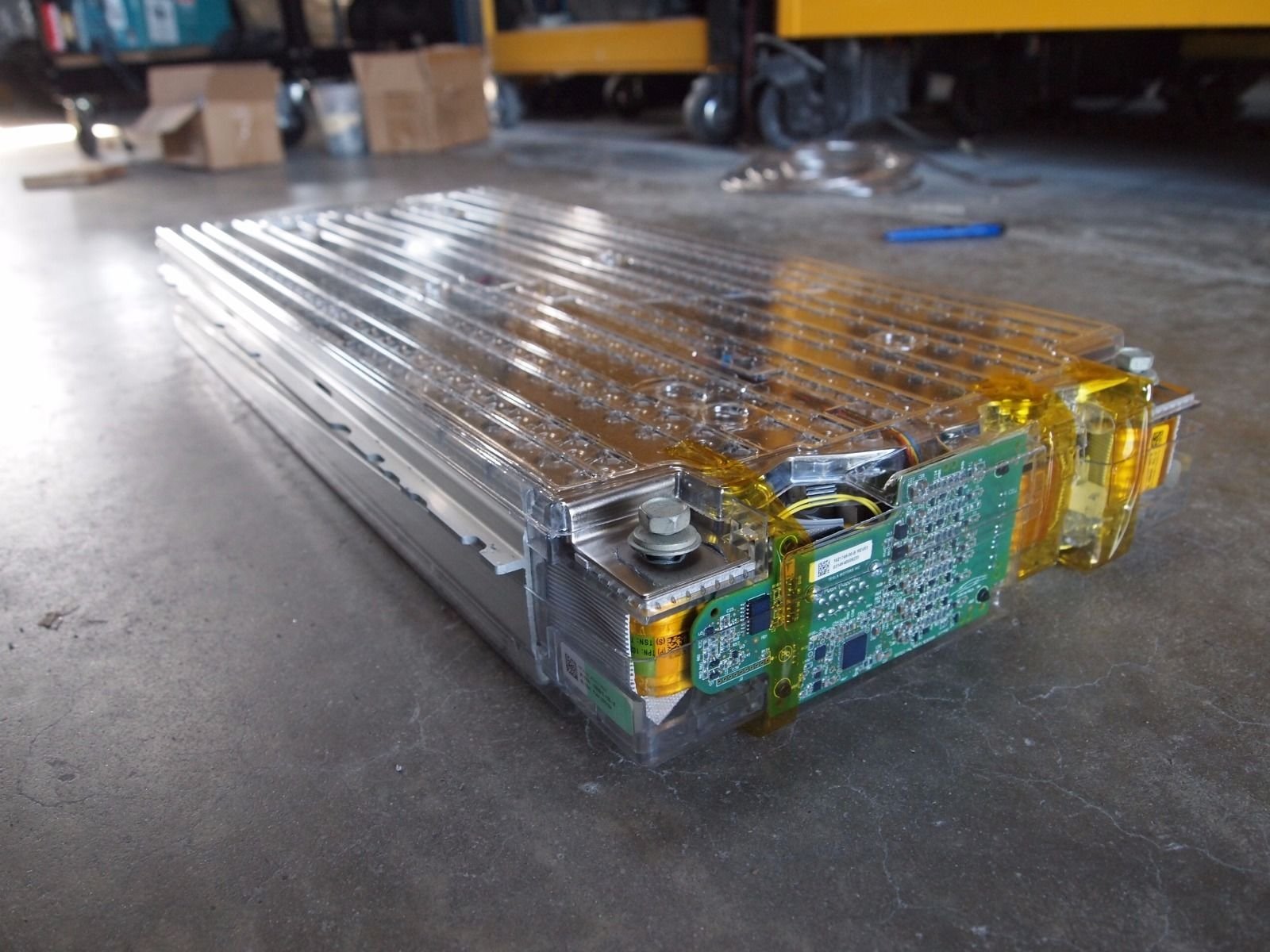 Side View of Tesla Battery Assembly | ||||||||||||||||||||||||||||||||||||||||||||||||||||||||||||||||||||||||||||||||||||
| ||||||||||||||||||||||||||||||||||||||||||||||||||||||||||||||||||||||||||||||||||||
| Copyright © 2011 - 2020 Ken Sochats | ||||||||||||||||||||||||||||||||||||||||||||||||||||||||||||||||||||||||||||||||||||


